Page 1
This blog post is about a box that could dynamically dim AC bulbs via computer control. The main purpose being to react to music. I will be providing code, and some schematics, and I hope other hobbyists will find this post useful.
(If you’d like to go straight to the technical stuff, simply start at page two)
First, a brief history.
My desire to make lighting that would react to music largely began in late 2003. A Perfect Circle released their album, Thirteenth Step. Upon first listen of the song, Blue, I pictured a series of lights reacting to the music, and blue shifting upon the chorus line of “She’s turning blue.” Years passed, and in 2008, I learned about the Winamp plugin, Discolitez , a plugin that allowed Winamp to control lights connected to a computer. I decided to build the most basic 8 channel circuit that ran off an LPT Port. As the circuit only required resistors, and LEDs, I knew I was capable of building it.
I built the circuit, but to my dismay, the result was lackluster at best. While it was simple to build something like a VU meter, the function of mapping LEDs to frequency bands looked like crap. With DiscoLitez, you were given the option of setting a thresholds on the volume that would trigger an LED, but the LED was either on, or off. I also accepted that using LPT port pins to drive any load directly was not best practice.
I read about using super brights with transistors, but the non-dimmable nature of the plugin really disappointed me. I made the following video using the song “Too Young” from the Venitian Snares. I chose the song as the music rapidly cuts in and out at the beginning and works well with the non-pwm lights. You could see towards the end of the video how badly the lights looked when the thresholds were met, and held..
▶ Watch video: https://www.youtube.com/watch?v=QpHPBTYZxv8
In the hope I could make the LEDs do more than just sit there, I began playing with the more advanced “Discolitez Pro” plugin which allowed such things as strobing the LEDS, and comparing data streams with logic gates. I wrote a “desktop,” as the configurations are known as to compensate for this. I set multiple thresholds for each band, and had those feed into a logic gate that would “AND” it with different timers. The idea was the louder a band got, the faster I’d strobe the bulb. Of course this methodology is opposite of how a PWM works. I knew that the pulsing was much too slow to have any sort of noticeable PWM, and that the software was not NEARLY powerful enough. Let alone, I wasn’t even fully introduced to the concept, yet.
▶ Watch video: https://www.youtube.com/watch?v=MMUAAxasmFA
The results didn’t look that bad in person, but I still wanted better results. I liked the idea of controlling hardware from an I/O port, so I went back to the LPT LEDs I had breadboarded. I connected it to a linux server, and found a program called “lptest” I could use to drive individual pins, and hence drive individual lights.
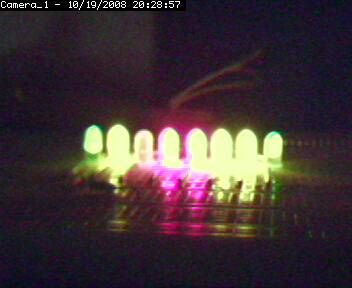
I had bought some opto-isolated solid state relays and connected one to an IO pin. I measured 13mA draw from a multimeter, which was on the edge of the Printer Port spec, but I felt was safe enough. I connected a string of Christmas lights to the SSR, and was excited by the fact I had command line control over an AC socket.
I knew I wanted to do more automation, but wanted a better way to drive hardware. Enter Microcontrollers…
Page 2
I went to the hardware hacker’s Mecca of Central Florida, Skycraft, and bought a hardware box to house my Solid State Relays in.
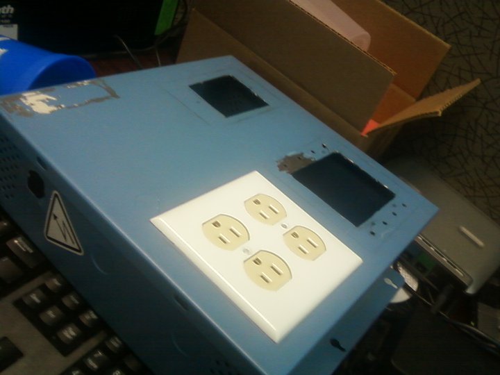
It was also during this time I learned that the Solid State Relays I were planning to use would not be ideal for dimming. I was learning about Zero-Crossing, and found the opto-22’s I had wouldn’t be fast enough to be fired in as many places as I would like for precise, 8-bit dimming.
I was donated a surface mounted TRIAC, and a MOC3021 opto-isolator to drive them. I built a reference circuit from the opto-isolator’s datasheet that allowed for the drive of inductive loads, but found that the circuit was producing a high pitched hum; it worked though. I connected the isolator’s on pin via resistor to a 5v+ source, and was able to tap a string of christmas lights on and off by touching the drive pin to 5v+.
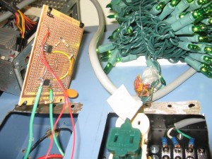
I decided it was time to start coding a PIC to phase control the TRIAC, and as I knew the ultimate goal was to drive the TRIACs serially, I started to look into PICs that supported UART. It just so happened that the spare PIC16F628s I had supported hardware UART, and were common chips.
I wrote VERY preliminary code that counted from 0-15, over and over at different speeds, and illuminated the count via LEDs. I coded the test routine to count 16 different intensity levels with, and display the count by binary on 4 LEDs. Other than that, it did not do much else besides set up a framework for future code. The video below showcases the hardware I was planning to use at the time.
▶ Watch video: https://www.youtube.com/watch?v=9aOCemqiZEw
As is shown, early on I planned on using a Mini-ITX motherboard I had to run a daemon to interpret network packets via programmable scripts, and use them to drive the PIC I was going to code. While I did not end up doing this, this idea ended up being used later on…
The next part of my code was of course a lot more complex. I had to find a way to detect the zero-crossing, and to turn on the Triac at the appropriate time. Of course, this was dependent on having zero crossing detection circuit. I scoured the internet, and came across this design by Michael Pearce:
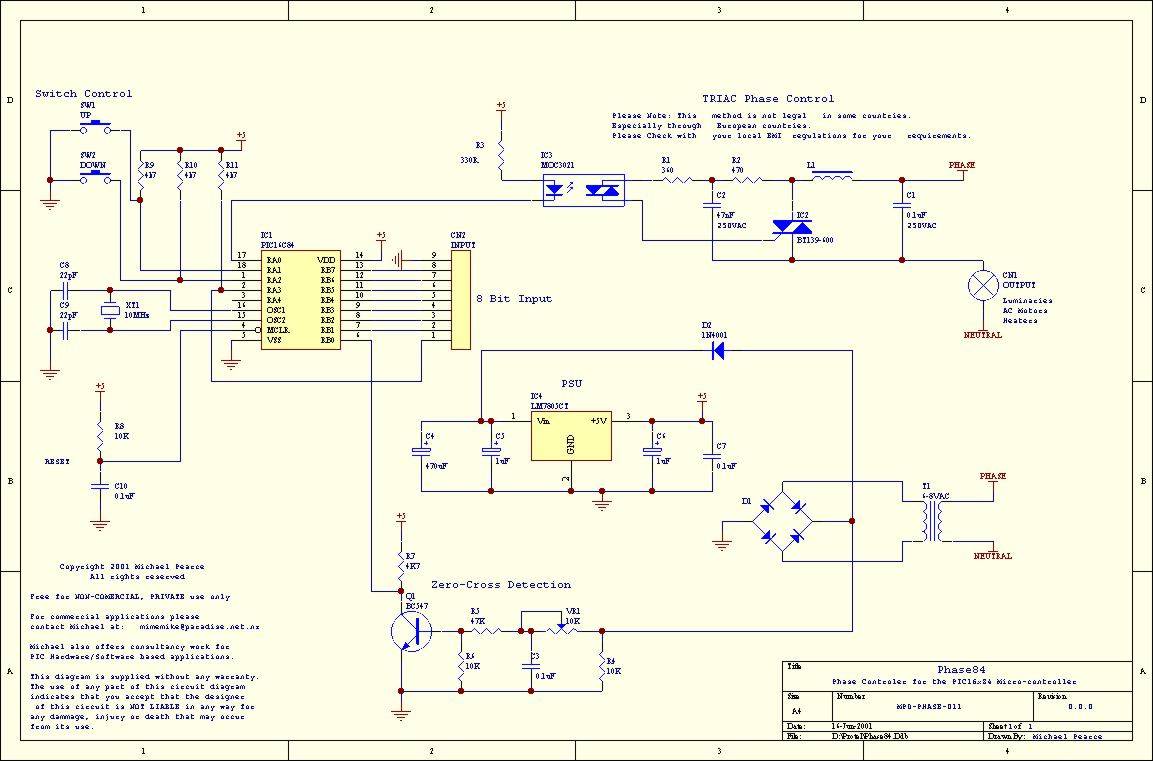
His design called for a transformer that would step down the 120v AC to 6-8v. While undesirable, I went with an oversized, over-kill transformer I bought from Skycraft. Even with the size, I still had more than enough space for it my project box. I know I could have gone with other ways of detecting zero crossing without a transformer, but as my number one goal was safety, I liked the idea of using the transformer as a natural protection as it would step down voltage efficiently.
In the design, the output of the transformer becomes rectified, and is eventually fed into a Transistor. When the base is driven low, it causes a pull up resistor to drive an input pin high. I would use this to trigger a hardware interrupt on the PIC. The design also used the stepped down voltage coming from the rectifier to drive a 7805 5v Regulator. As I was using a PSU rail at the time, I wasn’t planning on using this, but ultimately ended up using it for power as the ITX computer was taken out of the design.
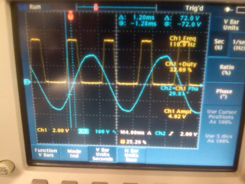
The circuit also has an adjustable 10k ohm pot used to fine tune the zero crossing detection. I connected the output of the circuit to an oscilloscope, with the AC Sine Wave on a second channel. I found that the Zero Crossing detection pin would rise before the actual crossing. On the scope, I measured these two events happened about 1.2ms apart. I knew I would have to account for this with an offset..
Sometime, around 4AM, last Thursday, I came up with this mess of a pseudo-code..

What I ended up planning was to set up a hardware interrupt to detect the zero-crossing, and then I’d copy whatever value I had for channel brightness (as was set by counter debug code) to a channel work register. After, I would set up a timer to account for the offset. When the offset finished, I started the actual routine.
The routine would then loop for how many levels of brightness I desired -1, at the time 16, and add one to the channel’s work register. I’d turn off that channel if the register did not overrun that pass, and turn it on if it did.
As an overrun would be any value that would exceed 255 (size of a byte) I used values 240-255 at the time to represent the 16 degrees of brightness, one of which being 0 of course. The routine would run for 15 loops, so if the value of 240 was used for a channel, by the end of the loop, the value would have become 255, and would have cut short before it overrun, hence never turn on. Likewise, if the maximum value of 255 was used, it would overrun the first loop, and hence be turned on. As 255 would overrun first loop every cycle, it would never turn off. These loops used a timer interrupt to space each half cycle 6.7% apart to have a linear scale of time for each value.
This would work great for this version of the code, (v0.4) but as I’d come to find I would run into problems once I increased to 256 levels of brightness.
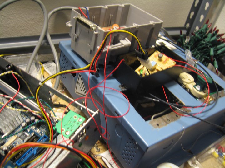
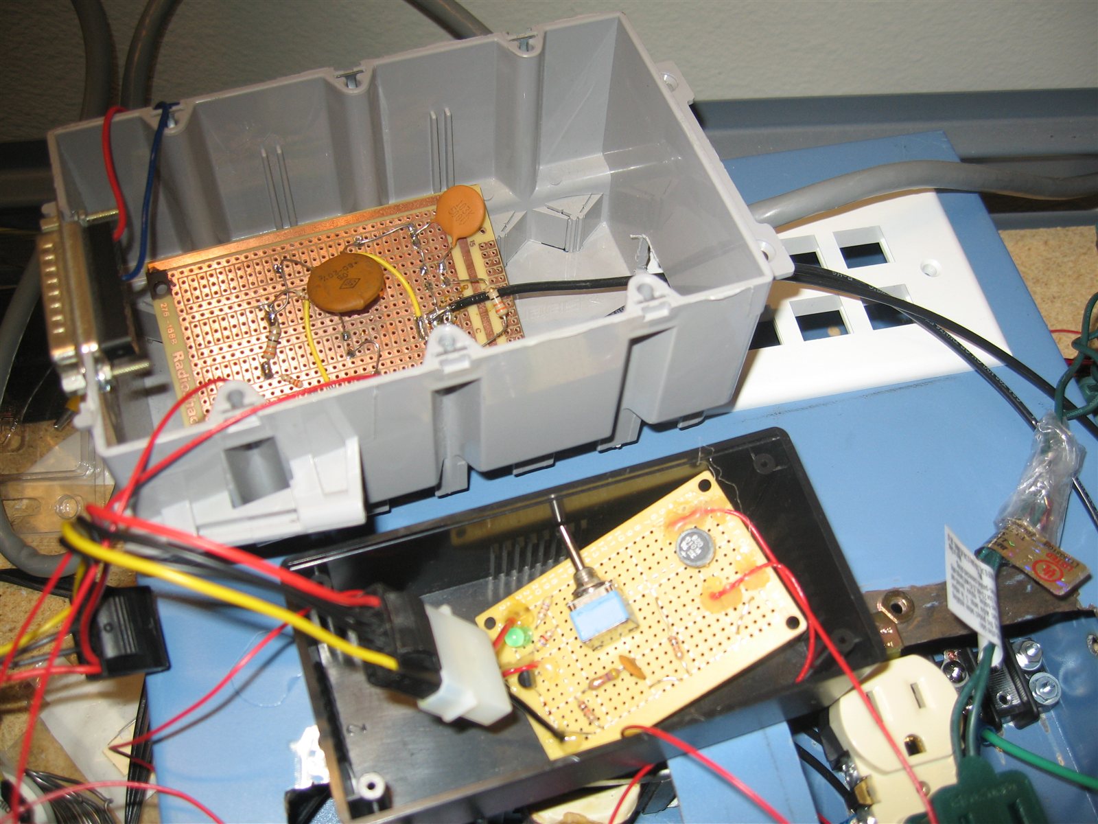
Th early hardware I was testing with:
Youtube clip of early dimming code in action:
▶ Watch video: https://www.youtube.com/watch?v=foCL79vxxK4
Next up, more permanent hardware, ICSP circuit, and optimization….
Page 3
From versions 0.5 to 0.7 of the code I went through assembly hell as I kept updating the code trying to get UART to work. As one could imagine, the process of removing the IC every few minutes to test code became tedious, and I started bending pins. I knew what I had to do. I had to implement ICSP so I wouldn’t have to worry about removing the IC from the board. It was also around this time I felt confident enough to make a logic board, so I did.
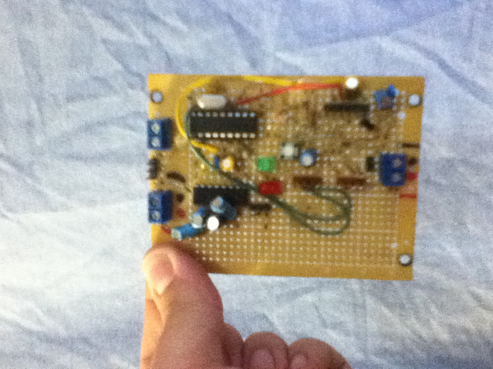
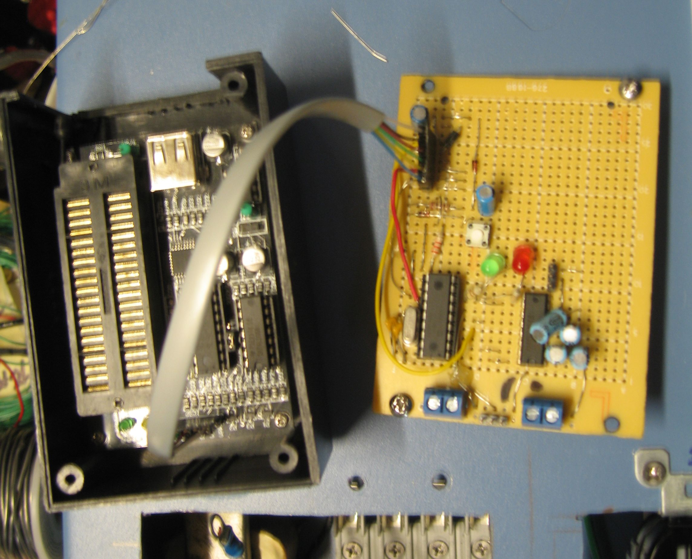
I ended up assigning version 0.6 to code that would not even execute as a way to save what changes I had been making before making other changes.
The problem I had was configuring the half dozen registers needed to get UART to function correctly, and actually….Reading-TFM. I wasn’t configuring the SPBRG register, and it is required to time the UART speed. The SPBRG register also needs to be calibrated differently based on the clock speed, which I hastily obtained the wrong value for. I also ended up using 3 interrupts. One for the hardware Zero Crossing detection on INT-0, another for the UART Receive, and the last for a timer for the Zero-Crossing offset. Configuring the registers to allow these interrupts, along with configuring and understanding the concepts like the “pre-scaler” took MANY hours of skimming through data sheets.
Also, my friend, the Interrupt Vector. :D
8-Bit PICs only have one. So what is an Interrupt Vector, you may ask? It’s a memory location where execution jumps to whenever an interrupt is triggered. As all three Interrupts jumped to the same address, I was forced to compare registers to see which Interrupt called execution to jump there.
ALSO, the registers being worked on when interrupted DO NOT automatically become saved. First thing I would do in the Interrupt routine is SAVE all work registers to temp addresses. I used Microchips’ own example to do this. Upon completion of the Interrupt routine, I would then restore the register values.
org 0x0004 ; memory location h004
; ***************************************************************************
; Interupt Service Routine MUST RUN FROM HERE ONLY !
;
; First run the Context Save Registers – you need to create the _temp filesisr_CS
movwf W_ISR_TEMP ; copy W to temp
swapf STATUS,W ; swap status to be saved into W
clrf STATUS ; bank 0
movwf STATUS_ISR_TEMP ; save status in bank O
movf PCLATH,W ; save pclath
movwf PCLATH_ISR_TEMP
clrf PCLATH ; clear to page 0 for ISR
movf FSR,W ; save FSR
movwf FSR_ISR_TEMP; User Code – MUST STAY WITHING ISR BOUNDARIES – DO NOT USE GOTOs OUT OF THE ISR – USE NO CALLS
; CONTEXT RESTORE REGISTERS
isr_END
movf FSR_ISR_TEMP,W
movwf FSR
movf PCLATH_ISR_TEMP,W
movwf PCLATH
swapf STATUS_ISR_TEMP,W ; swap status temp to w to set org bank
movwf STATUS ; movW to status
swapf W_ISR_TEMP,F ; restore W
swapf W_ISR_TEMP,W
retfie ; return from isr; End of ISR
;****************************************************************************
I built out the box around this time over the course of a few weeks. I took my time, and collected the hardware I needed from Skycraft, Radioshack, Mouser, and Home Depot. As safety was excessively on my mind, I used high grade electrical wire to feed power to the box, and grounded both the top, and the bottom of the box.
I chose to house the Triacs on a perfboard, with an electrical power bus soldered to the bottom of the board (Which I unfortunately do not have a picture of.)
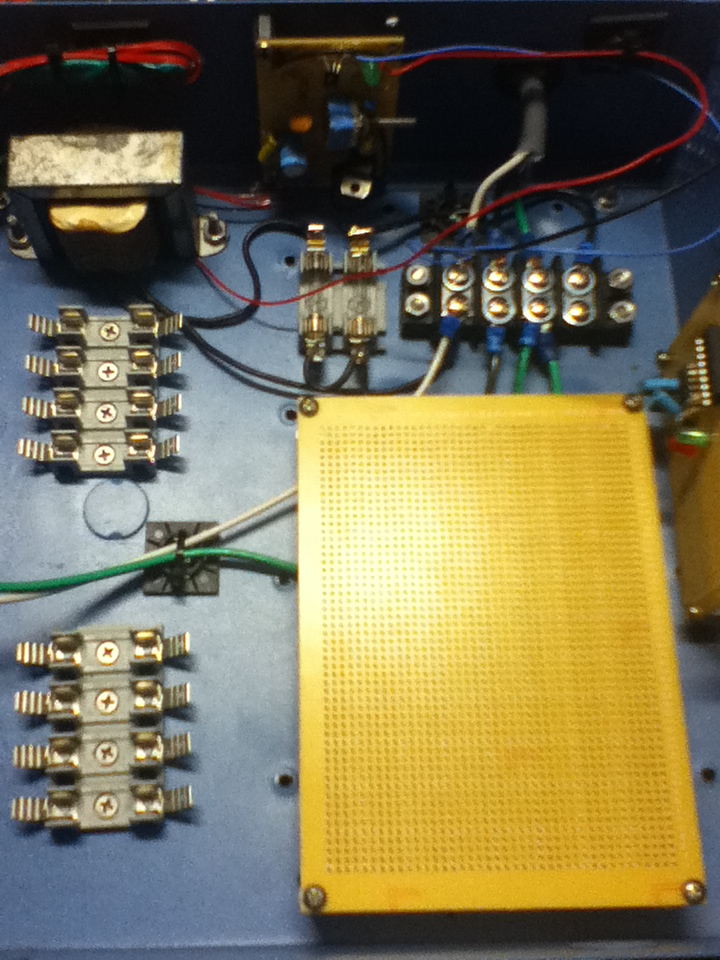
I used 10 fuses.
- A 10-amp fuse for the Triac board that drove all the outputs.
- An individual fuse per each of the 8 channel.
- Another for for the transformer that drives the zero crossing detection, and 5v rail.
——————————————–
The triacs are by STMicroelectronics, Model BTA16-600B, and they are being driven by Fairchild MOC3021 opto-isolators. After reading through lots of example circuits, I decided to go with the minimalistic, resistive only load circuit found in the datasheet for the MOC3021M.
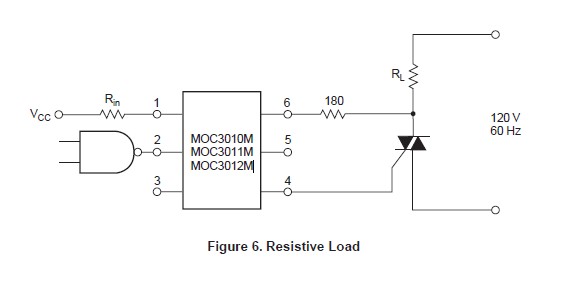
I started mounting the components, and although not visible from the top of this PCB, a striped 16 gauge, stranded electrical wire runs the horizontal length of it, soldered on with a 100 watt soldering gun. I used this as a power bus. I then soldered bare 18 gauge, stranded wire that runs from this bus to each Triac, and then to the output screw terminals. The screw terminals at the front of the board are digital I/O inputs for each channel, and for power and ground.
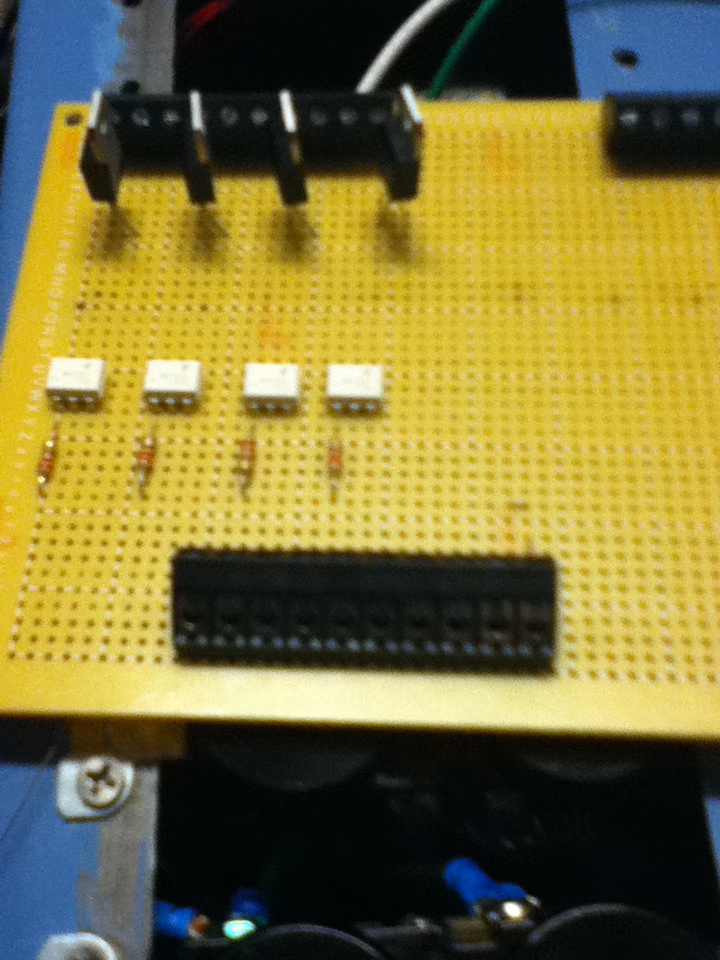
To drive the opto-isolators, I used NPN transistors to switch their ground pins, and drove the transistors from the PIC Micro.
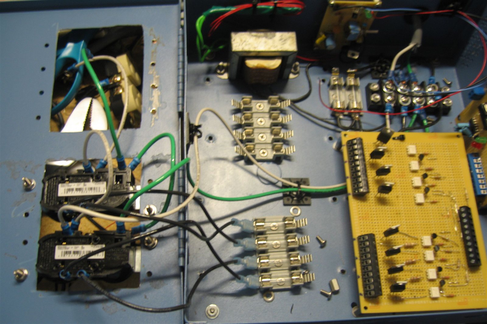
Below is the box with power and zero crossing detection board on left wall, logic board on back wall, and triac board coming off the base of the box.
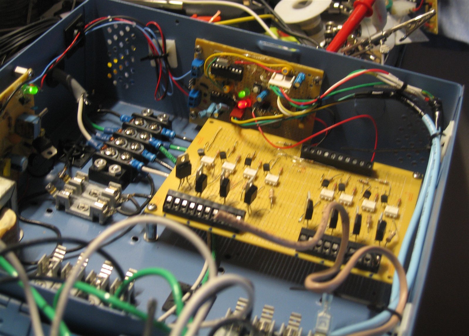
Different angle with transformer in upper right.
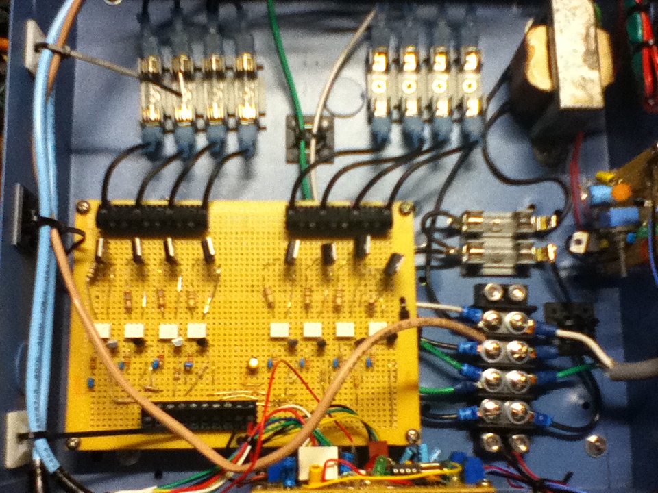
With the box safely assembled, and without AC mains cable hanging everywhere, I concentrated on optimizing the assembly code….
Page 4
The routine that overruns the channel registers, and drives the channels was moved to the main routine and done in software. For 8-bit resolution of the phase, it would need to run 255 times per each of the 120 half cycles a second. If done via an interrupt timer, it would interrupt execution 30600 a second! After realizing this, and knowing I had only 5 MHz to work with, it shifted my thinking. This routine WAS the main routine, and other routines were interrupting it. Not the other way around.
The number one concern of my code was to get a value, and to hold the dim level of a light based on that value. The hardware zero-cross interrupt, and the phase offset was required to time this, but once running, the dim routine could be run in software. A complete execution of the “main” dim code would be done once per zero cross, and would not restart until the next cross. As the zero cross, and phase offset would only run once per dim code execution, I wasn’t TOO concerned about timing my code to account for those interruptions, but the UART code I knew would be more chaotic.
As incoming UART transmissions would interrupt my main software PWM code randomly, I had to account for this, and keep timing on track. I originally had UART set up for 9600 Baud, and when translated to bytes (9600 / 8), would at max interrupt my code 1200 times a second. When taking into account that each half cycle was 1/120th of a second, this would only amount to 10 bytes per each run of my main routine.
I had the PIC using a 20 MHz crystal, but the PIC divides that clock by 4 internally, so, I only ended up with a 5 MHz running speed. My main routine had to execute 120 times during this space. By dividing the 5,000,000 cycles by the 120 half-cycles, I ended up with 41666.666~ cycles to play with. To be able to draw to 255 timed positions in the phase, I had to execute this code….255 times in this space. So 41666.666 / 255 equals…… 163.3987 clocks. Lets just say 163. ;-)
As was mentioned previously, UART would only to interrupt the chip 1200 times a second, which amounts to once per 4166.666~ cycles. Thus, I would only need to worry about offsetting the delay caused by this once per the 163 cycles I had to work with. I ended up upping my baud speed to 19200 later to allow 20 bytes per half cycle, and as 11 bytes were required to change the dim level (as described in README,) and the dim level could be changed once per half cycle, I was able to achieve a dim refresh rate of 120hz.
To optimize everything, I used the friendly opcode sheet below as I coded:
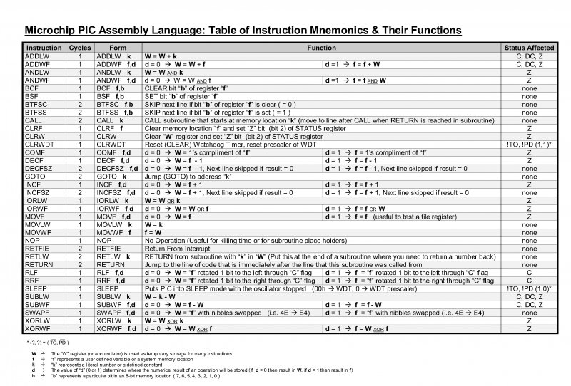
I timed the routines accordingly, leaving only the dimming “TIMER_LOOP_ROUTINE,” and the routine for processing the UART bytes in software.
;==========================================================
;MAIN Loop
START
call TIMER_LOOP_ROUTINE; 80 Clocks (Typical) OR 96 Clocks upon last loop (Including Call)call UART_ROUTINE; Routine for RS-232, 82 Clocks (Including Call)
goto START; + 2 clocks (=164)
;***************************************************************
;***************************************************************
I timed the routines to run at consistent speeds. The timer loop runs at 80 clocks per draw, and an additional 16 clocks the last draw cycle. Those additional clocks are used to load new dim values to be used after the next zero-cross.
Delays are added throughout the routine to delay the code where necessary to ensure the routine always runs at a predictable speed. The same is done with the UART routine, but differently. The UART code takes 82 clocks with call, regardless if a byte was received or not.
In actuality, the UART routine only uses 49 clocks, but if a byte was received, the interrupt will consume 31 clocks. I factor this into the timing.
With this code in place, I began work on the client code, and whipped up a python script that would randomly send dim values to the box:
▶ Watch video: https://www.youtube.com/watch?v=e2v5Yv54QX4
Next up, Music Sync, and Home Automation. :D
Page 5
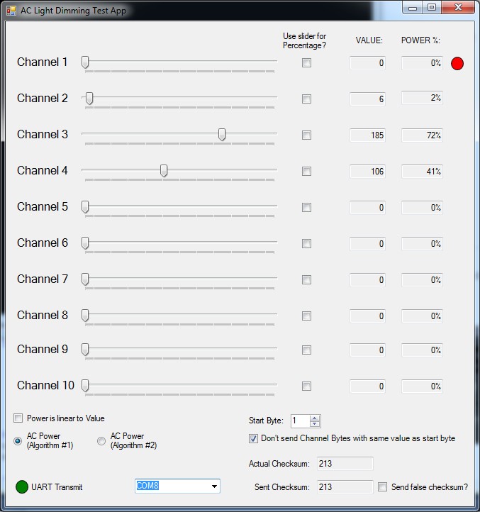
For the python script, I used the python module, PySerial to communicate to the port. As I couldn’t get PySerial to work on Windows 7, I decided to write a quick VB app. I added to the app the ability to send faulty start bytes, to allow channels to have the same value as the start byte, and to allow a false checksum to be sent. The box passed the test every-time.
I needed a way to get Discolitez to send dimmable values via serial, and adhere to the protocol I devised. A breakthrough came when I learned that Discolitez Pro had a way to pipe UDP packets out through a network socket. I fired up Wireshark and found the packet it was generating was 18 bytes in length.
Out of the 18 bytes, 16 represent 8 channels. Each channel is represented by two bytes that represent an 8-bit value. For each channel, the first of the two bytes represent the first nibble of the value, and the second byte represents the second nibble. The nibble is sent in plain text as ascii. So “0-F” will be sent. By combining the first and second nibble, an 8 bit value of the channel can be determined.
The 17th byte will always be 0x0D, and the 18th byte will always be 0x0A.
Using this knowledge, I wrote a script that took in the UDP packet, interpret it, and spit it right back out to serial using my protocol. The results were great! ^_^
▶ Watch video: https://www.youtube.com/watch?v=Gc-V1yyfYSk
Although… I found that the frequency bands didn’t allow for too much uniqueness, and I was limited to use Winamp as my audio player.
I decided I wanted a way for the code to work wirelessly, so I found a guide to get UART out of a WRT54G series router. Using the SD-Card hack, I was able to install Python and run my script off of it.
–UDP over Wifi w/ WRT54G-TM SD Card and Max232n
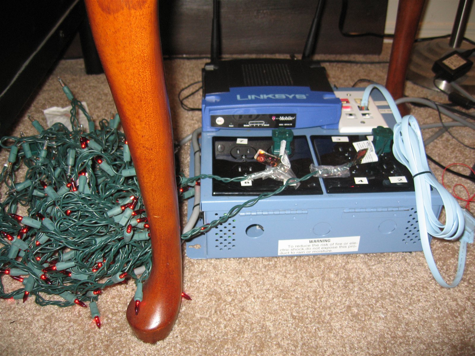
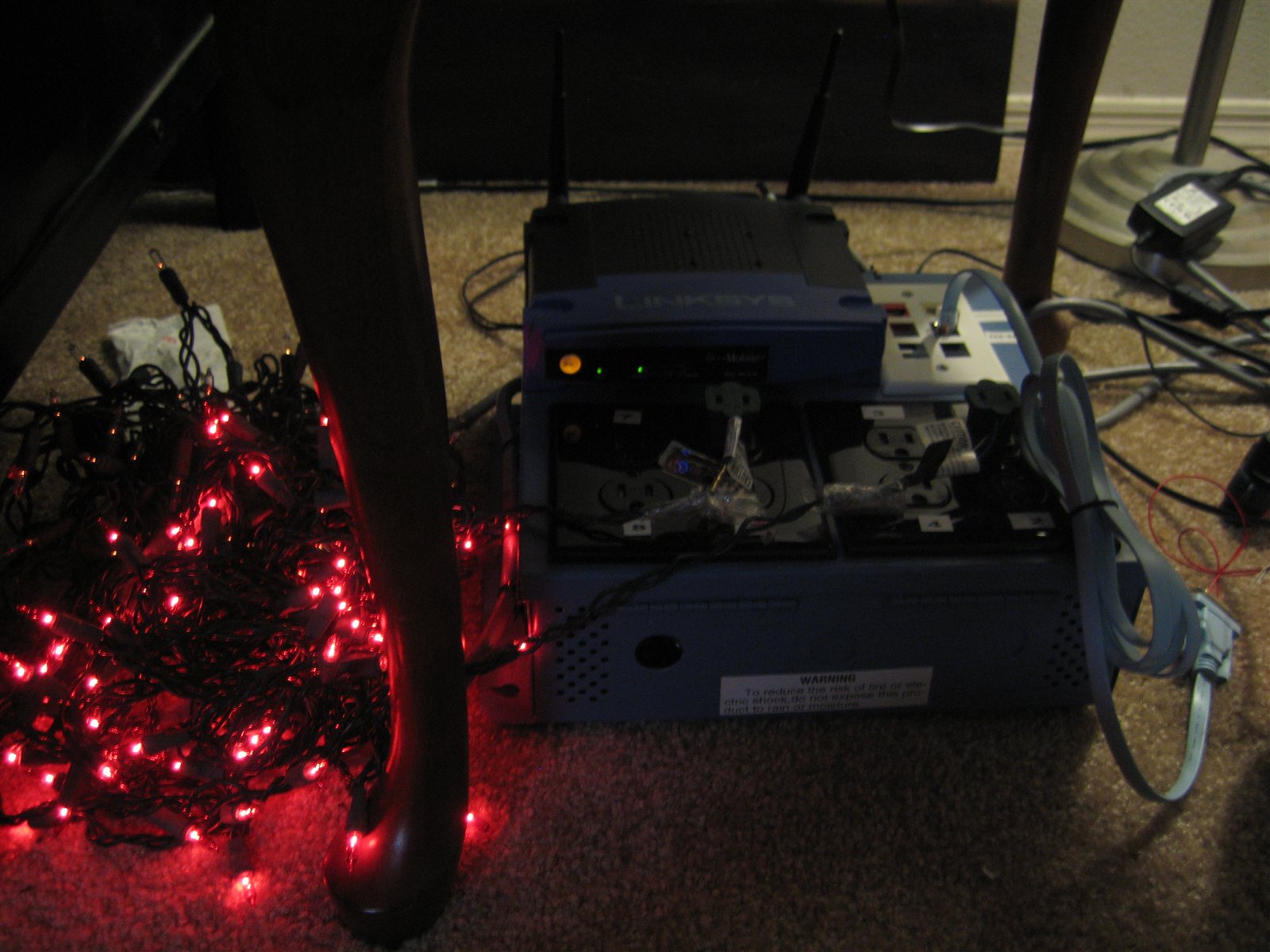
Late night a few weeks later, I was on a Skype video call with my friend, and FamiLAB member, “Tetsu” Dan, and showed him a floor lamp I had hooked to my light dimming box. I forwarded the UDP port through NAT on my home router, and challenged him to code a home automation webapp for my iPod touch.
A short time after corresponding back and forth, he was able to control my lamp using the sencha touch api for NodeJS. I am very pleased by the results. The video screen capture below was recorded that night:
Lastly, Hardware based music sync.
Page 6
On October 10th, 2011 I visited Hack A Day, and found a project that used an MSGEQ7 chip from Sparkfun to break a line-in signal into 7 bands, and graphically represent the values onto an LCD screen. As there was a Halloween party the next weekend, and the host wanted my lights, I knew what I had to do.
I ordered a few chips, and as Arduinos were all the rage with my hackerspace, I went to the darkside and ordered one.
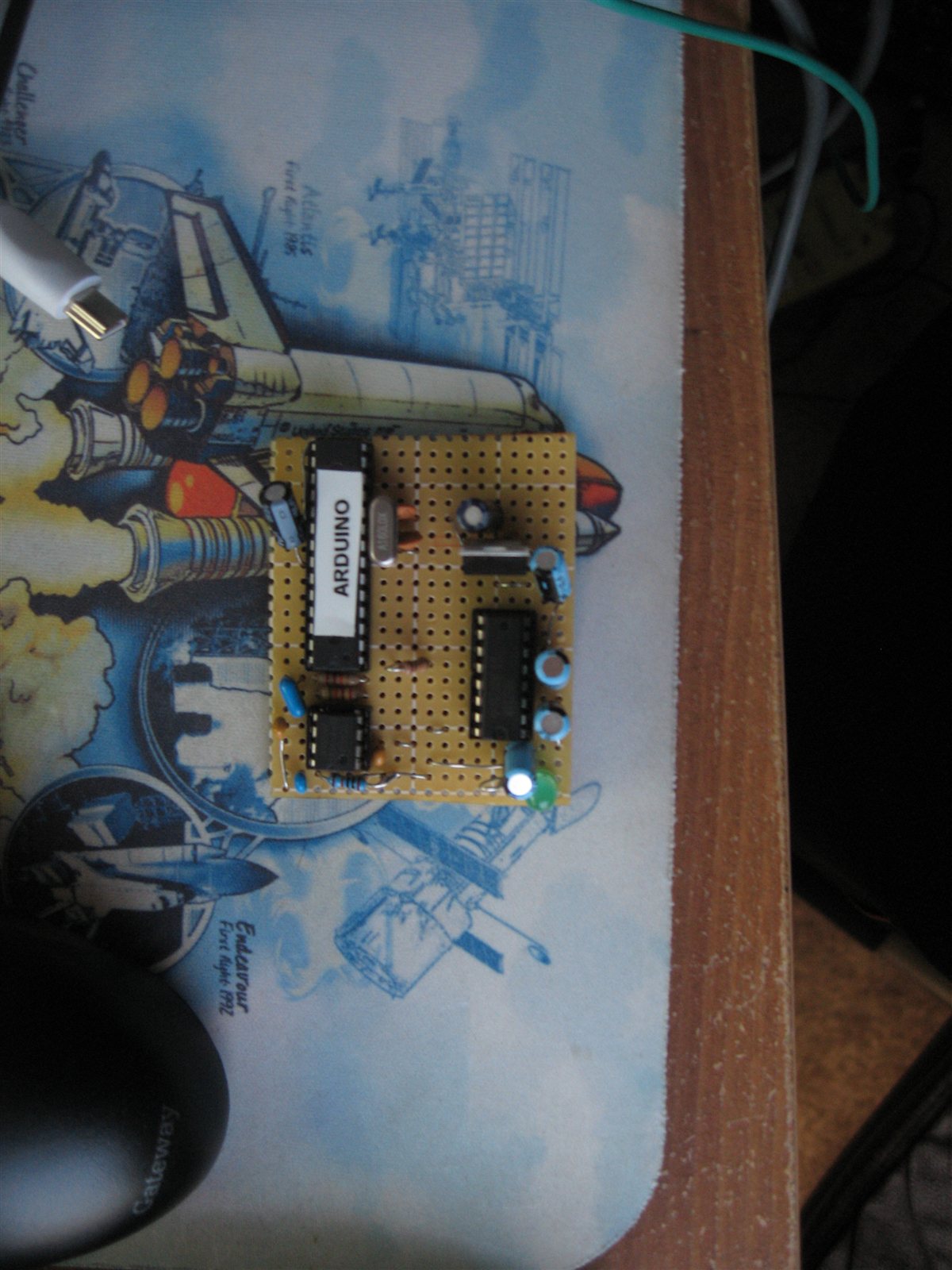
I assembled a prototype circuit, and found a reference for help. It didn’t take me long to write code that took the intensity of 7 bands, and translate it into UART my box understood:
▶ Watch video: https://www.youtube.com/watch?v=7A9m8YXDeRY
I completed the prototype just in time for the party, took the Arduino with breadboard, and set it up. It worked better than I could have ever imagined and had a better frequency isolation than Discolitez.

▶ Watch video: https://www.youtube.com/watch?v=tVzEp0hbRbg
After the party, I moved the circuit to a more permanent perfboard:
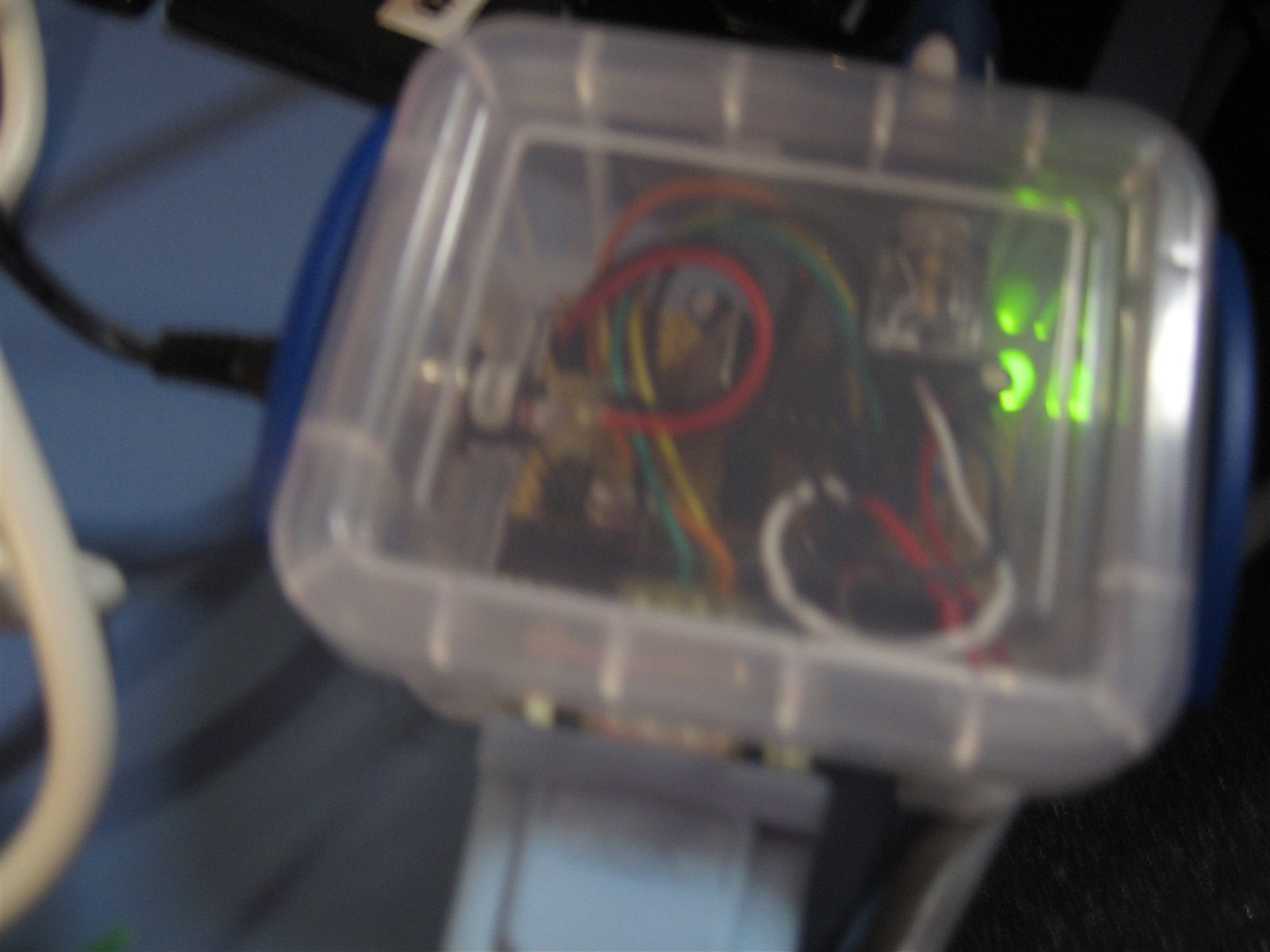
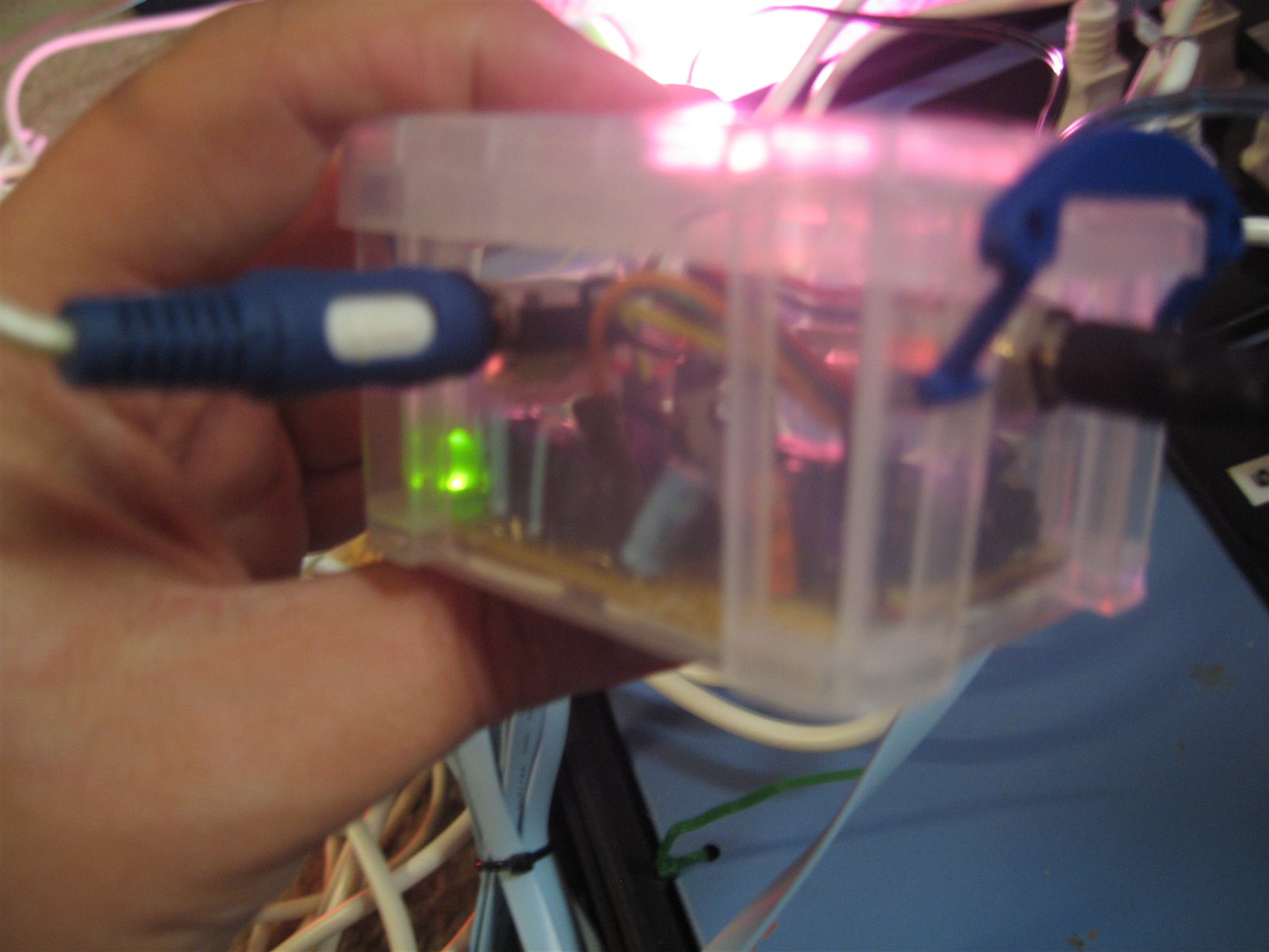
There you have it. As any big project, it will never be finished in my mind, and will be ongoing. :)
Code:
Github Repo of PIC16f628a ASM + HEX
Github Repo of Dan’s Home Automation Mobile Application
To Do:
– PIC Code
- Add routine to adjust Phase offset via software; Save value to eeprom
- Clean up timing code; fix a couple of bugs
– Python Socket Listener
- Update code to allow for home automation specific routines
- Rewrite the code to be more streamlined; make into an api
– Arduino Code
- Build DMX512 Box
One last vid, the lights on our FamiLAB, Fami-Tree :D